The 1947 - Present Chevrolet & GMC Truck Message Board Network


Register or Log In To remove these advertisements.

Go Back   The 1947 - Present Chevrolet & GMC Truck Message Board Network > General Truck Forums > Engine & Drivetrain > LSx Swaps

Web 67-72chevytrucks.com


Reply
 
Thread Tools Display Modes
Old 07-28-2013, 12:11 PM   #1
cjohnson6772
Registered User
 
cjohnson6772's Avatar
 
Join Date: Dec 2010
Location: NC
Posts: 666
fan wiring - diode

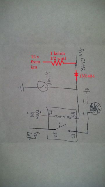
I tried wiring in my trinary switch yesterday. Now my primary fan no longer works at all haha. After thinking about it I think the diode may be preventing the current from returning to ground at pin C1-42. I'm just concerned about wiring the trinary ground straight to pin 85 of the relay along with the pcm wire. I don't won't to mess up my PCM! How should I wire this in without adding another relay?!?!?
Posted via Mobile Device
Attached Images
 

Last edited by cjohnson6772; 07-28-2013 at 12:21 PM.
cjohnson6772 is offline   Reply With Quote
Old 07-28-2013, 12:30 PM   #2
ls1nova71
Registered User
 
ls1nova71's Avatar
 
Join Date: Dec 2009
Location: Independence Mo
Posts: 4,119
Re: fan wiring - diode

I don't think removing the diode would hurt anything. You're just grounding it before the PCM, but if you want to leave it, try turning the diode around.
__________________
My '72 short bed build. http://www.ls1tech.com/forums/conver...6-0-4l80e.html

5.3 swap into my RUSTY '71 C10
http://ls1tech.com/forums/conversion...71-c-10-a.html
ls1nova71 is offline   Reply With Quote
Old 07-28-2013, 02:48 PM   #3
dayj1
Senior Member
 
Join Date: Jul 2009
Location: Athens, AL
Posts: 499
Re: fan wiring - diode

You are correct that you don't want to connect the trinary switch directly to the relay along with the PCM control for the fan. The diode is backwards in the diagram above. In addition, your PCM will eventually throw a code about the fan control circuitry because it uses the relay coil as a pull-up resistor to 12V. To defeat that check, you can add a resistor to 12V between the diode and the PCM. I updated your diagram to show what I'm talking about. Changes are in red.
dayj1 is offline   Reply With Quote
Old 07-28-2013, 05:46 PM   #4
cjohnson6772
Registered User
 
cjohnson6772's Avatar
 
Join Date: Dec 2010
Location: NC
Posts: 666
Re: fan wiring - diode

Quote:
Originally Posted by dayj1 View Post
You are correct that you don't want to connect the trinary switch directly to the relay along with the PCM control for the fan. The diode is backwards in the diagram above. In addition, your PCM will eventually throw a code about the fan control circuitry because it uses the relay coil as a pull-up resistor to 12V. To defeat that check, you can add a resistor to 12V between the diode and the PCM. I updated your diagram to show what I'm talking about. Changes are in red.

Ok I've been doing some thinking since it would be a royal pain to run another ign wire to my pcm based on location:

First off I think I'm going to change to pin 33 on C2 to turn on my second fan since my first fan already stays on most of the time anyways. Also, could I just wire the diode and resistor in parallel instead of adding another ign wire? If my thinking is correct, this should be the same since the pcm would always see the 12V from pin 86 on the relay passing through the 1kOhm resistor.

If I did leave the diode and resistor out all together, would it actually damage the pcm or just throw the code?
cjohnson6772 is offline   Reply With Quote
Old 07-28-2013, 06:41 PM   #5
clinebarger
Senior Member
 
Join Date: May 2009
Location: Fort Worth, TX
Posts: 6,370
Re: fan wiring - diode

Quote:
Originally Posted by cjohnson6772 View Post
Ok I've been doing some thinking since it would be a royal pain to run another ign wire to my pcm based on location:

First off I think I'm going to change to pin 33 on C2 to turn on my second fan since my first fan already stays on most of the time anyways. Also, could I just wire the diode and resistor in parallel instead of adding another ign wire? If my thinking is correct, this should be the same since the pcm would always see the 12V from pin 86 on the relay passing through the 1kOhm resistor.

If I did leave the diode and resistor out all together, would it actually damage the pcm or just throw the code?
It will just throw codes, Dayj1,s way will work, Running 2 relays is what I would do.
clinebarger is offline   Reply With Quote
Old 07-28-2013, 06:47 PM   #6
dayj1
Senior Member
 
Join Date: Jul 2009
Location: Athens, AL
Posts: 499
Re: fan wiring - diode

Quote:
Originally Posted by cjohnson6772 View Post
Ok I've been doing some thinking since it would be a royal pain to run another ign wire to my pcm based on location:

First off I think I'm going to change to pin 33 on C2 to turn on my second fan since my first fan already stays on most of the time anyways. Also, could I just wire the diode and resistor in parallel instead of adding another ign wire? If my thinking is correct, this should be the same since the pcm would always see the 12V from pin 86 on the relay passing through the 1kOhm resistor.

If I did leave the diode and resistor out all together, would it actually damage the pcm or just throw the code?
The PCM grounds the fan relay control line(s) to turn on the fan(s) in response to engine coolant temperature. In addition, when the fan(s) are supposed to be off, the PCM monitors the state of the fan control line(s) to detect a fault in the circuit.

Under normal circumstances, the control line is held at a logic high because the relay coil acts as a pull-up resistor on the control line. If you add a trinary switch to the PCM's control line, and the switch closes, the trinary switch will ground the control line. The PCM doesn't know anything about the trinary switch and sees this as a problem. Then it throws a code (P0480, I think).

To answer your first question, the resistor and diode in parallel would not work. The diode, when oriented correctly, is there to stop the trinary switch from sending ground back to the PCM. A resistor in parallel would defeat that because it would provide a current path around the diode. In addition, the resistor would drop the voltage low enough that that the PCM probably couldn't even turn on the fan anymore.

For your second question, if you leave them both out, you'll get a code but it shouldn't damage the PCM.

The real problem in all this is that when the PCM throws the code, it defaults to the fans always being on until the fault is cleared. So, your fans will always run with the ignition on after you get the code.
dayj1 is offline   Reply With Quote
Old 07-28-2013, 08:28 PM   #7
cjohnson6772
Registered User
 
cjohnson6772's Avatar
 
Join Date: Dec 2010
Location: NC
Posts: 666
Re: fan wiring - diode

Just came back in the house and saw the last two responses. Thanks guys! I have connected the trinary straight to pin 85 for the secondary fan relay. I will likely add another relay or diode/resistor in the coming weeks, but I just needed to get something wired up to have my a/c guy charge it this week. To be honest I doubt that I should ever see the high pressure before both fans are running anyways. I'm running a 195 t-stat and the first fan kicks on at 200 and the second fan kicks on at 210. I figure I would see 210 before I would see high a/c pressure since my condenser is basically the same cross section as my radiator. Anyways, I would have never thought about wiring in the other resistor (I guess I don't really understand "pull up resistors"), but I will add it when I have more time to run the extra hot wire.

Thanks again guys.
cjohnson6772 is offline   Reply With Quote
Old 07-28-2013, 09:31 PM   #8
dayj1
Senior Member
 
Join Date: Jul 2009
Location: Athens, AL
Posts: 499
Re: fan wiring - diode

Quote:
Originally Posted by cjohnson6772 View Post
Just came back in the house and saw the last two responses. Thanks guys! I have connected the trinary straight to pin 85 for the secondary fan relay. I will likely add another relay or diode/resistor in the coming weeks, but I just needed to get something wired up to have my a/c guy charge it this week. To be honest I doubt that I should ever see the high pressure before both fans are running anyways. I'm running a 195 t-stat and the first fan kicks on at 200 and the second fan kicks on at 210. I figure I would see 210 before I would see high a/c pressure since my condenser is basically the same cross section as my radiator. Anyways, I would have never thought about wiring in the other resistor (I guess I don't really understand "pull up resistors"), but I will add it when I have more time to run the extra hot wire.

Thanks again guys.
To address your comments on the difficulty of running a new IGN wire, I wouldn't go through the trouble of a new dedicated wire or extra fuse or anything like that. The 1K ohm resistor will only pull somewhere around 0.015 amp. Just run an 18 or 20 gauge wire from pin 86 of the fan relay to the banded side of the diode that you spliced into the control line (with the resitor inline with the new wire). You may have already known that, but I just wanted to clear up that you don't need a 10 guage wire and a 15 amp fuse or something
dayj1 is offline   Reply With Quote
Old 07-28-2013, 09:38 PM   #9
cjohnson6772
Registered User
 
cjohnson6772's Avatar
 
Join Date: Dec 2010
Location: NC
Posts: 666
Re: fan wiring - diode

Quote:
Originally Posted by dayj1 View Post
To address your comments on the difficulty of running a new IGN wire, I wouldn't go through the trouble of a new dedicated wire or extra fuse or anything like that. The 1K ohm resistor will only pull somewhere around 0.015 amp. Just run an 18 or 20 gauge wire from pin 86 of the fan relay to the banded side of the diode that you spliced into the control line (with the resitor inline with the new wire). You may have already known that, but I just wanted to clear up that you don't need a 10 guage wire and a 15 amp fuse or something
I do appreciate the clarification! Unfortunately my PCM is tucked into the fender cavity by the battery on the passenger side. My fuse block for the engine harness is over on the driver side against the firewall. My trinary switch is attached to the bottom fitting of my condenser in front of the core support so the ign wire will just be a long pull unless I can find something to piggyback off of. It is manageable but just a pain in the but to run a wire all the way across the engine bay.
cjohnson6772 is offline   Reply With Quote
Reply

Bookmarks

Thread Tools
Display Modes

Posting Rules
You may not post new threads
You may not post replies
You may not post attachments
You may not edit your posts

BB code is On
Smilies are On
[IMG] code is On
HTML code is Off

Forum Jump


All times are GMT -4. The time now is 01:16 PM.


Powered by vBulletin® Version 3.8.11
Copyright ©2000 - 2024, vBulletin Solutions Inc.
Copyright 1997-2022 67-72chevytrucks.com