 |
|
|
#1 |
|
Registered User
 Join Date: Feb 2011
Location: Joshua Tree Ca.
Posts: 719
|
Help with speedometer
I need some advice on my Gen IV 5.3 4l80 swap. My TCM wiring color and pin #s don"t come out right.
|
|
|

|
|
|
#2 |
|
meowMEOWmeowMEOW
Join Date: Sep 2009
Location: MKE WI
Posts: 7,128
|
Re: Help with speedometer
How are we supposed to know what didn't come out right? Give me something to work with dude. Didn't come out right meaning
a) didn't match the diagram you had b) didn't match a harness you had made/sourced c) didn't end up the way you wanted (if you modded/made it)
__________________
'66 Short Step / SD Tuned / Big Cam LQ4 / Backhalfed /Built 4l80e / #REBUILDEVERYTHING  |
|
|

|
|
|
#3 |
|
Registered User
 Join Date: Feb 2011
Location: Joshua Tree Ca.
Posts: 719
|
Re: Help with speedometer
the print out that i have shows pin #5 BU wire circuit 381 vehicle speed sensor
my TCM pin #5 OG Original harness with PCM & TCM Hope that helps |
|
|

|
|
|
#4 |
|
Registered User
 Join Date: Feb 2011
Location: Joshua Tree Ca.
Posts: 719
|
Re: Help with speedometer
When i bought the 5.3 it did not have the original 4l60 with it so I picked up a 4l80 I sent the ecm & tcm to lt1 swap to remove vats ect and he reprogramed the tcm I sent him a message yesterday but he has not responded.
|
|
|

|
|
|
#5 |
|
meowMEOWmeowMEOW
Join Date: Sep 2009
Location: MKE WI
Posts: 7,128
|
Re: Help with speedometer
The 4l80e uses an ISS/OSS instead of a single VSS (which i believe the 60es still used), so the wiring won't match if thats actually the case. The secondary sensor needs to be wired in and pinned to the ECM. Even if he did change the tune for the 4l80e, it needs to see both sensor and compare the input and output speed.
Also are you running an E38 pcm or something different? Pins 27 and 28 on the ECM are the GMLan connection to the TCM.
__________________
'66 Short Step / SD Tuned / Big Cam LQ4 / Backhalfed /Built 4l80e / #REBUILDEVERYTHING  |
|
|

|
|
|
#6 |
|
Senior Member
 Join Date: Sep 2005
Location: Lewisville, Nc
Posts: 10,237
|
Re: Help with speedometer
Please also include the year mame and model of the harness and ecm just saying stock doesnt help us
__________________
David fuller Ase Certified Mechanic Click here to help support our board!! 1971 Chevy c-10 under going a 4.8l LSx swap Build Thread http://67-72chevytrucks.com/vboard/s...d.php?t=421305 2007 Honda Accord my daily 145kmiles 2002 Honda Accord 4 door With 330k(sisters car) 2005 toyota Avalon 228k( brothers car) 2002 Sububran 5.3 245k 2000 Tahoe 5.3l 378 General manager for Marco's Carwash & lube |
|
|

|
|
|
#7 | |
|
Registered User
 Join Date: Feb 2011
Location: Joshua Tree Ca.
Posts: 719
|
Re: Help with speedometer
Quote:
|
|
|
|

|
|
|
#8 |
|
Senior Member
Join Date: May 2009
Location: Fort Worth, TX
Posts: 6,370
|
Re: Help with speedometer
Pin 5 of the TCM will be the Replicated TOSS (Transmission Output Shaft Speed) signal too the ECM, Do not mess with that circuit.
If you looking for a VSS Output to a aftermarket Speedometer, Look at Pin 57 on the Black Connector of the ECM, This is the VSS Output for the ABS Module for 3 channel ABS, Puts out over 100,000 PPM (forget the actual output) 4L60E's with a E38/T42 set-up have ISS Speed Sensors, But they are 12vdc Hall Effect, Not a A/C Sine Wave ISS like on a 4L80E & they are wired different. What year harness are you using? |
|
|

|
|
|
#9 |
|
Registered User
 Join Date: Feb 2011
Location: Joshua Tree Ca.
Posts: 719
|
Re: Help with speedometer
The harness came with the motor 2008 Avalanche
Thanks for responding Last edited by cru_zn_29; 07-13-2016 at 11:09 PM. |
|
|

|
|
|
#10 |
|
Registered User
 Join Date: Feb 2011
Location: Joshua Tree Ca.
Posts: 719
|
Re: Help with speedometer
I was going to use a speedometer from a 1992 era Caprice so i can put it in my original dash and look somewhat like it came that way.
|
|
|

|
|
|
#11 |
|
Registered User
Join Date: Dec 2002
Location: Cactus Patch So. Az
Posts: 4,749
|
Re: Help with speedometer
Take some pic, sounds like a good fix
__________________
53 TuTone Extended Cab 350 4-Spd 3:08 (SOLD) 53 Chevy Moldy pearl green ZZ-4 4L60E 9" 3:25 55 GMC 1st Black Mll (ZZ4) ZZ6 TKO 600 5 sp 3:73 62 Solidaxle Corvette Roman Red (327 340hp 4spd 3:36) C4 & C5 suspension tube chassis LS 3 4L70E 65 Corvette Coupe 327 350hp 4spd 4:11 78 Black Silverado SWB (350/350) 5.3 & 4L60E 3:42 2000 S-Type 3.0 (wife cruiser) 2003 GMC SCSB 5.3 4L60E 3:42 |
|
|

|
|
|
#12 |
|
Registered User
 Join Date: Feb 2011
Location: Joshua Tree Ca.
Posts: 719
|
Re: Help with speedometer
I went back a checked my wiring front and rear speed sensors are wired in and wire from pin 57 to the speedometer. Pins 27 &28 are hooked to GMLan at TCM Now the speedometer reacts like a tac and the odometer now shows .8 of a mile. Something not right
|
|
|

|
|
|
#13 |
|
Senior Member
Join Date: May 2009
Location: Fort Worth, TX
Posts: 6,370
|
Re: Help with speedometer
A factory '92 GM speedo needs a 4000 PPM signal, Pin 57 puts out way more than that, I have made aftermarket speedo's work off this signal using a harness matched too the ECM/TCM & it had a Yellow/Black wire in pin 57. (The same color ABS VSS Output wire GM has used for decades)
Just looked at the ECM pinouts for a 2008 Avalanche, Only certain Brake Codes had the Output, Even if your Harness has the wire.....You had your Modules Re-Flashed, So I don't know what it's outputting, And I'm not you sure will ever get a 4000 PPM signal, Maybe a Tuner will chime in? |
|
|

|
|
|
#14 | |
|
Senior Member
 Join Date: Jul 2009
Location: Athens, AL
Posts: 499
|
Re: Help with speedometer
Quote:
Unless HP tuners has changed the functionality of their speedo functions in the last couple of years, it is not possible to change the PPM setting on a Gen IV ECM. I worked around this on a 5.3 swap into my '57 BelAir with a hardware solution. It's fairly easy to modify the 128K ppm signal by dividing with a binary counter IC such as the one in this link: http://www.mouser.com/ProductDetail/...NSjtvhkGLr8%3d If you feel handy enough with a soldering iron to build your own circuit board, I can draw you a schematic and post it. It'd cost you about $10 in parts. Otherwise, there are some ready made solutions out there like this one, but they're a little more expensive at $90-ish. |
|
|
|

|
|
|
#15 | |
|
Registered User
 Join Date: Feb 2011
Location: Joshua Tree Ca.
Posts: 719
|
Re: Help with speedometer
Quote:
|
|
|
|

|
|
|
#16 |
|
Registered User
Join Date: Dec 2009
Location: Independence Mo
Posts: 4,119
|
Re: Help with speedometer
I was going to say get a Dakota Digital SGI-5 or something similar , but if Jonathan has a way to do it for $10 in parts, then that's the way to go! I'd be interested in seeing it too.
__________________
My '72 short bed build. http://www.ls1tech.com/forums/conver...6-0-4l80e.html 5.3 swap into my RUSTY '71 C10 http://ls1tech.com/forums/conversion...71-c-10-a.html |
|
|

|
|
|
#17 |
|
Senior Member
 Join Date: Jul 2009
Location: Athens, AL
Posts: 499
|
Re: Help with speedometer
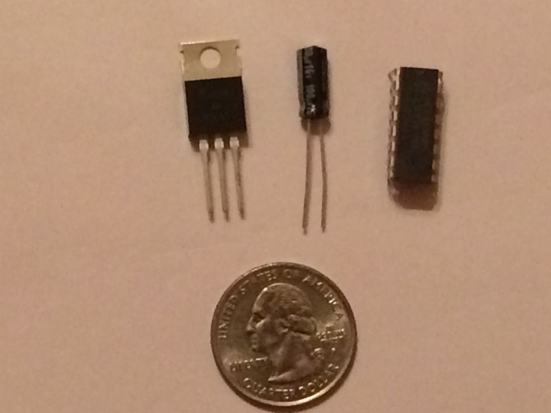
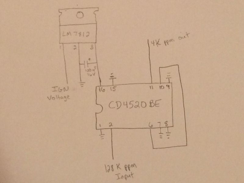
Here's what I have used successfully to convert a 128k ppm signal to 4k ppm. You could most likely get by with just the binary counter IC that I linked above, but, to be safe, I added a voltage regulator to make sure that the IC always sees a steady 12V supply that doesn't fluctuate up or down.
Here's a pic of the electronic parts needed with a quarter to show scale:  The heart of this project is a CD4520 binary counter IC that costs $0.55 http://www.mouser.com/ProductDetail/...NSjtvhkGLr8%3d You'll also need a 1 amp 12 volt regulator that costs $0.64 http://www.mouser.com/ProductDetail/...ZyYOsz27OnY%3d And a 100 uF capacitor that costs $0.19 http://www.mouser.com/ProductDetail/...VjV0Fq7QH7Y%3d You'll also want some type of prototype board to assemble the project. I'm sure mouser has something, but I used one of these from a local Radio Shack for $2.49 https://www.radioshack.com/products/...ant=5717554885 That's a grand total of $3.87 plus shipping if you're handy with a soldering iron. Sorry for the hand drawn schematic, but it's the best I could do on short notice   Using the prototype board I linked above, you end up with a board about 1.75" square and mine has been working for a couple years now without a hiccup. |
|
|

|
|
|
#18 |
|
Registered User
Join Date: Dec 2002
Location: Cactus Patch So. Az
Posts: 4,749
|
Re: Help with speedometer
Do I see a new product here!!!!
Put your name on them and offer them to the folks!
__________________
53 TuTone Extended Cab 350 4-Spd 3:08 (SOLD) 53 Chevy Moldy pearl green ZZ-4 4L60E 9" 3:25 55 GMC 1st Black Mll (ZZ4) ZZ6 TKO 600 5 sp 3:73 62 Solidaxle Corvette Roman Red (327 340hp 4spd 3:36) C4 & C5 suspension tube chassis LS 3 4L70E 65 Corvette Coupe 327 350hp 4spd 4:11 78 Black Silverado SWB (350/350) 5.3 & 4L60E 3:42 2000 S-Type 3.0 (wife cruiser) 2003 GMC SCSB 5.3 4L60E 3:42 |
|
|

|
|
|
#19 | |
|
Registered User
 Join Date: Feb 2011
Location: Joshua Tree Ca.
Posts: 719
|
Re: Help with speedometer
Quote:
|
|
|
|

|
|
|
#20 |
|
Registered User
 Join Date: Feb 2011
Location: Joshua Tree Ca.
Posts: 719
|
Re: Help with speedometer
Ok i made up the small circuit board It slowed way down but still thinks it is a slow tac when i revup the motor When i drive up the 300' driveway speedo goes about 25 mph. I am still missing something.
|
|
|

|
|
|
#21 |
|
Senior Member
 Join Date: Jul 2009
Location: Athens, AL
Posts: 499
|
Re: Help with speedometer
If the speedometer moves when you just rev the motor, that's definitely not normal. It sounds like your speedometer may be hooked to the tach output instead of the speedometer. You said above that you verified that pin 57 of the black connector was connected to the speedometer so it sounds like time to see whats going on with a scanner that can read live data.
|
|
|

|
|
|
#22 |
|
Registered User
 Join Date: Feb 2011
Location: Joshua Tree Ca.
Posts: 719
|
Re: Help with speedometer
Yes it is pin 57 YE/BK. The E38 ECM printout shows VSS Output to abs system 128k ???
|
|
|

|
|
|
#23 | |
|
Senior Member
 Join Date: Feb 2014
Location: new smyrna beach fl / 29 palms cal
Posts: 1,727
|
Re: Help with speedometer
Quote:
__________________
Hand made A/C vent manifolds for 64-66 trucks adapts any aftermarket A/C to OEM vent |
|
|
|

|
 |
| Bookmarks |
| Thread Tools | |
| Display Modes | |
|
|