
 |
Register or Log In To remove these advertisements. |
|
|
|
|||||||
 |
|
|
Thread Tools | Display Modes |
|
|
#1 |
|
Registered User
 Join Date: Mar 2005
Location: apple valley, ca
Posts: 2,670
|
My caster mod (with pictures)
On Rob's Make It Handle thread, he mentioned that if he were to ever do a mod to increase caster, he would move the lower arm forward and the upper arm aft. This got my brain spinning, and I decided to do the lower arm mod. Here's what I did:
To start, I disassembled the lower control arms and blasted everything clean. Take a note of the locations of the factory-located spot faces, as they are going to change to a new location on the shaft. 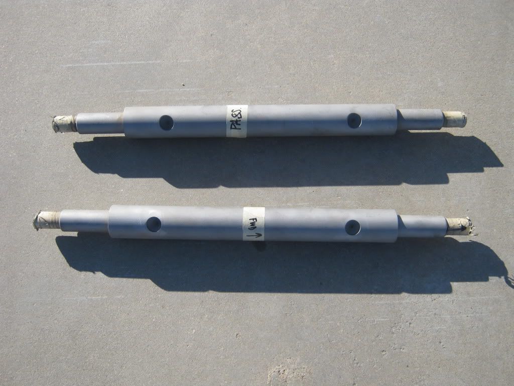 I sent the shafts to a friend who is a machinist. The intent is to move the lower control arm forward .75", so the spot face holes will need to move .75" on the shaft. I discovered that the factory spot faces on my shafts did NOT line up with the locating pins on the crossmember at both the forward and aft locations. Only the front actually used the pin, and the aft point was not a pin at all, just a raised area that acted more like a spacer instead of a locating pin. I wanted positive pin retention, so it was important that both front and aft points pinned into the cross shaft. Here's what you need to do: First, spin the cross shaft 180 degrees opposite of the factory spot faces so you have a nice clear area to work with. Then, make your .75" measurement from the centerline of the aft hole. Remember, you're moving the arm forward, so the new spot face will be closer to the edge of the cross shaft in relation to the original factory spot face. Once you have set this measurement, you must go to the crossmember and measure the center-to-center distance between the front and aft pins. My measurement was 9.0" exactly. So, for the forward spot face hole, I went 9.0" from the centerline of the newly located hole. Here is a side-by side shot of the factory locations versus the new locations. The upper shaft is the factory location, the lower shaft is the new location. 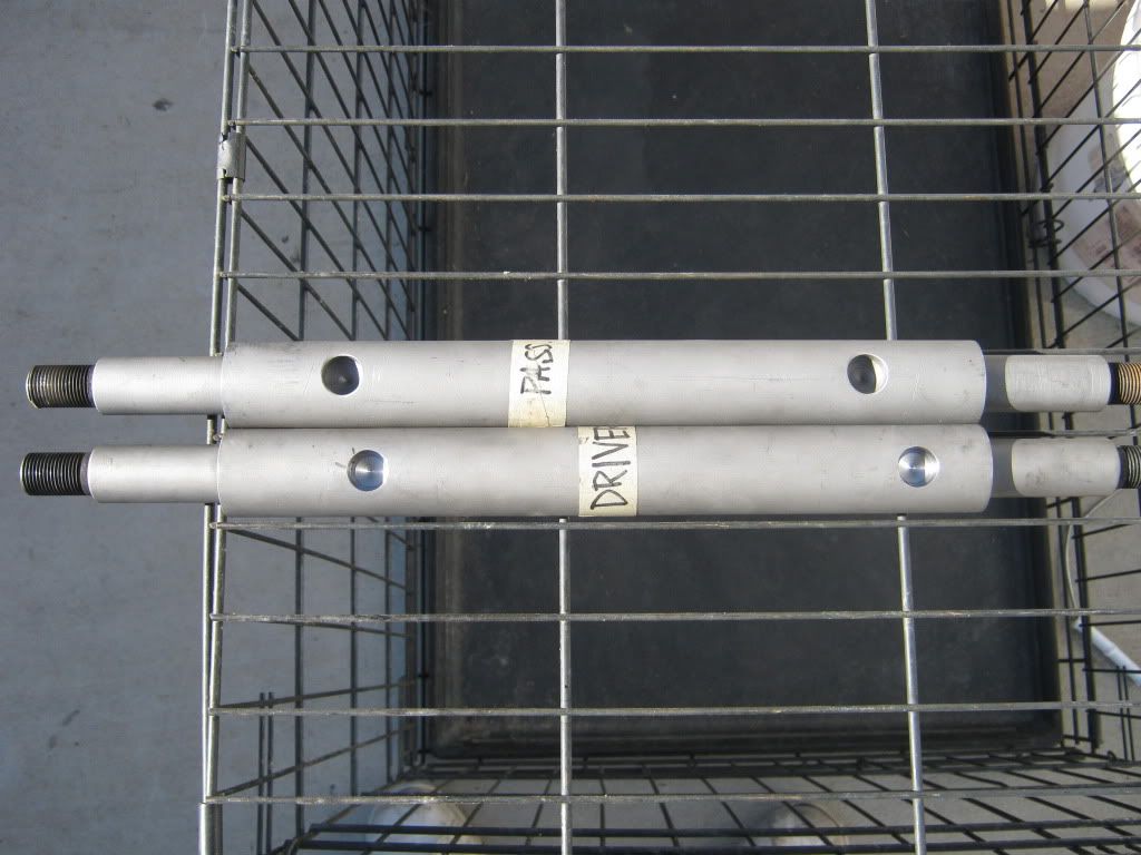 In order to do this mod, you have to remove the saddles that are riveted to the center crossmember. The lower control arm cross shafts are kept from spinning by a stud that locates itself in the spot-faced holes in the lower control arm shaft. Here, you can see a picture of the front crossmember showing the two bolt holes for the u-bolts and the rivet head for the locating stud I mentioned earlier. The stud side is not visible in this picture. 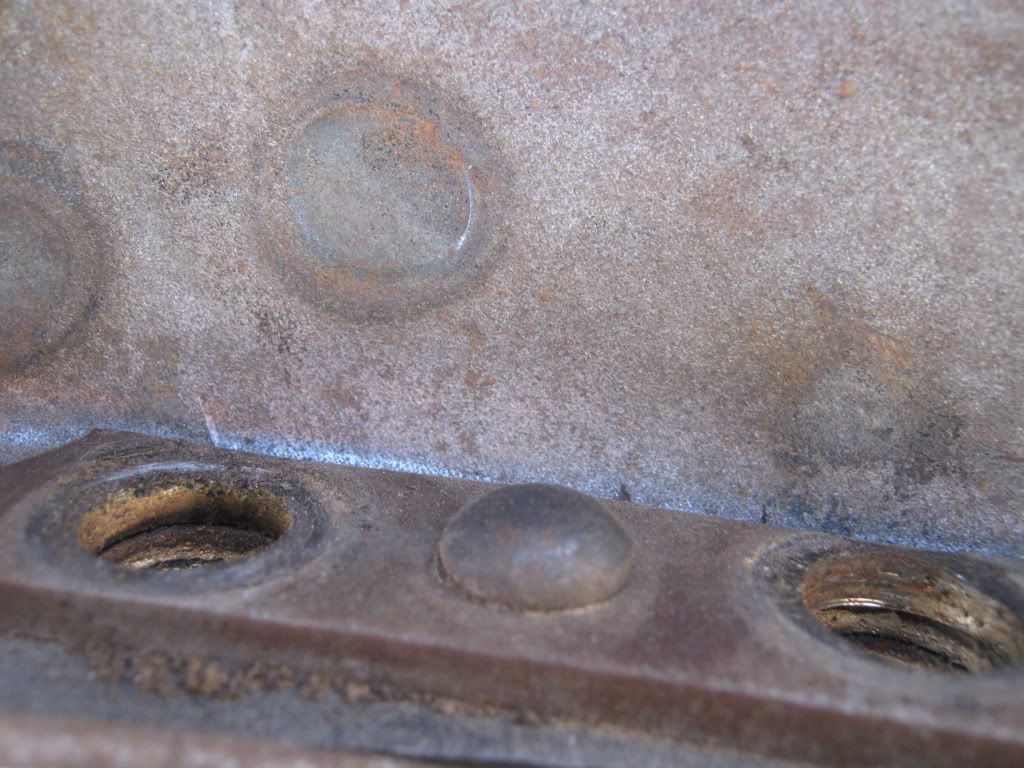 In order to get the saddles removed, you have a few options. You can grind the heads off and drive out the rest of the rivet. Or, you can fire up the torch and melt the rivet heads off, then drive out the rest. I opted for the torch. I learned quickly that even with the head and tail of the rivet melted off, the rivet stems did not come out without a fight. I had to warm up the rivet stem with the torch and shoot them out with an air chisel. The rivets go through 4 layers of steel (doubler plate, saddle, and and 2 layers of the crossmember). Once you get them out, here's what the pieces look like after a few minutes in the blaster: 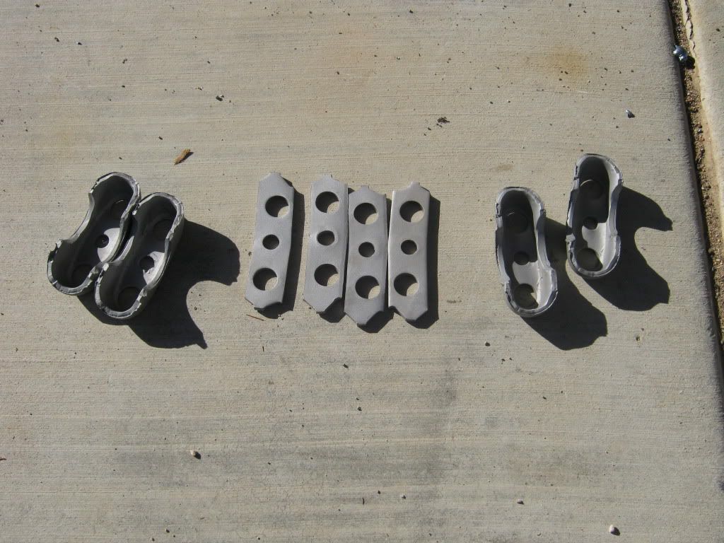 Here's what you'll see when the saddles, doubler, and rivets are removed. I decided that I was going to use a 7/16-20 X 1.50" socket head cap screw as the new locating pin, so the center hole in this picture needed to get opened up to a 7/16 to ensure that bolt would fit nice and tight. The light area in the front is the lip on the crossmember, which will be cut away. Sorry for the dark picture, my lighting was a little goofy. 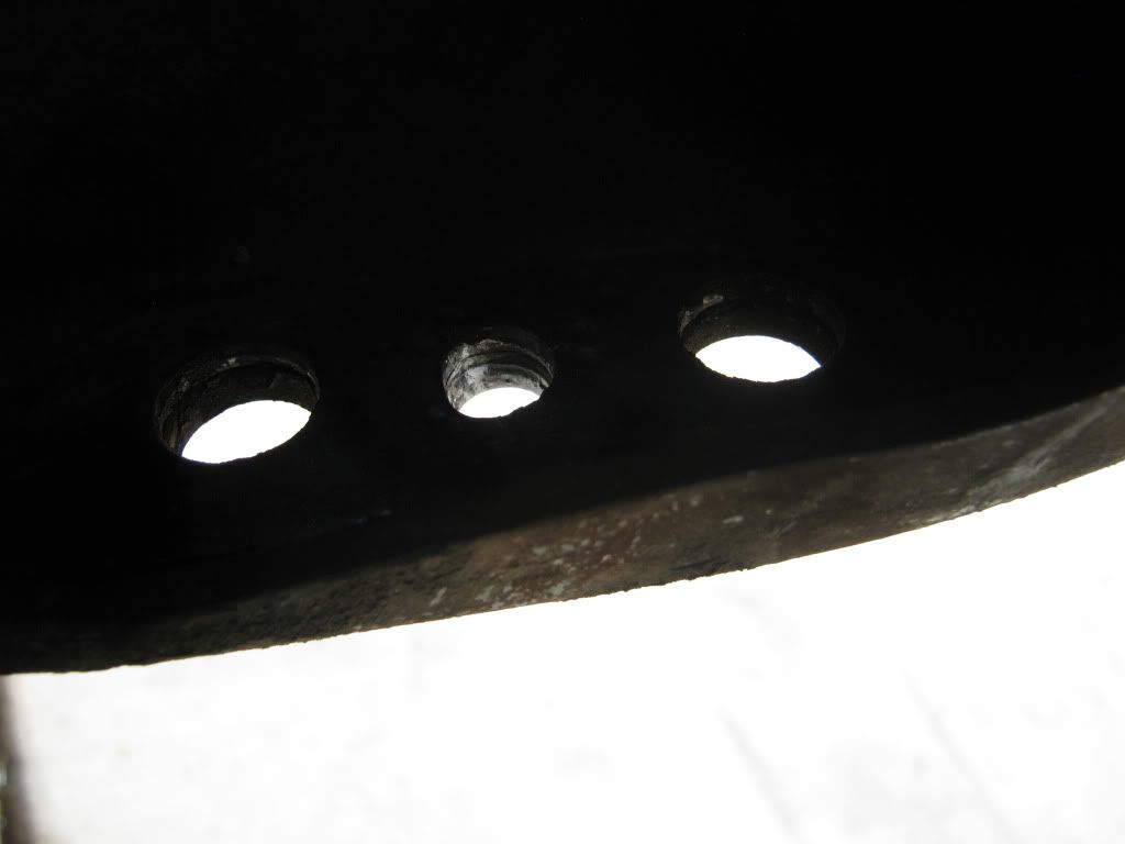 Moving the control arm forward will cause the aft side of the control arm to get really close to the center crossmember, so I removed the lip and blended out the cut to eliminate any sharp edges that could cause a stress riser. You will only need to cut the lip back to where it meets the second metal layer. 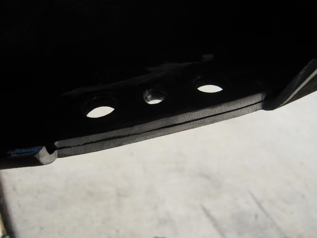 Here's a shot of the saddles back in place on the crossmember. This shows the bolt in place of the old rivet locating pin. For added insurance, I used Loctite and a stover nut. Here's a shot of the finished installation: 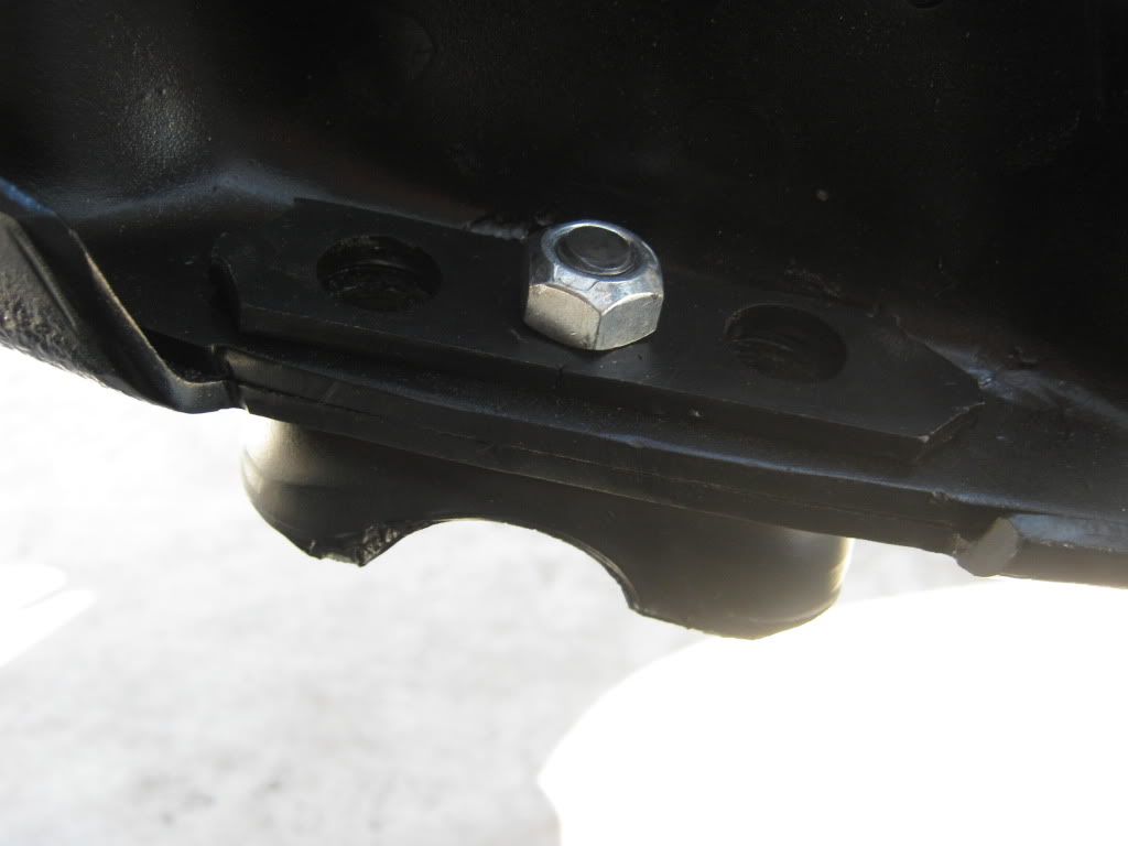 In this shot, you can see the head of the fastener, which will locate perfectly in the new spot face positions in the lower control arm cross bar. 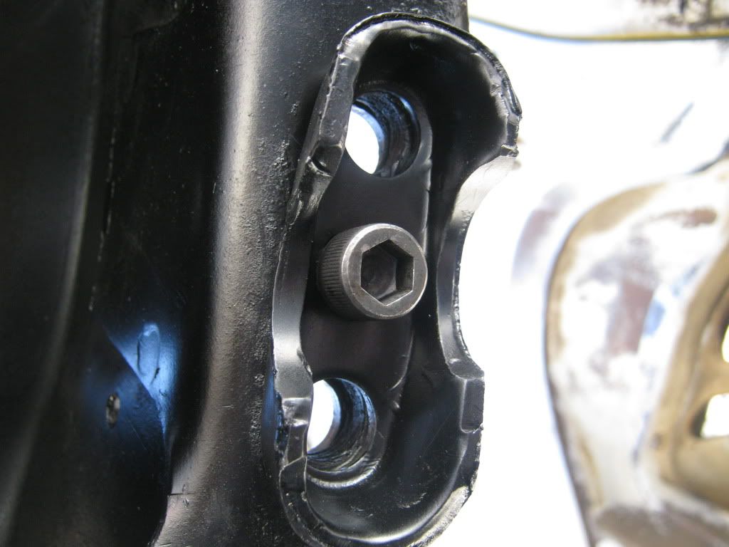 While the control arms were out, they got blasted and painted. New Energy Suspension bushings were installed and all the balljoints were replaced with Moog parts. Then the moment of truth arrived, and it was time to install the control arms and see if the caster mod was a success. Everything fit perfect. The clearances were excellent, and the locating pins lined up exactly as planned. Here is a shot of the driver's side control arm. You can see just how much the control arm moved forward. 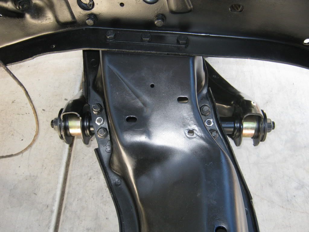 Here's a close-up shot of the back-side. If you recall, I had to clearance the crossmember. I now have plenty of room with the control arm at full up/down. 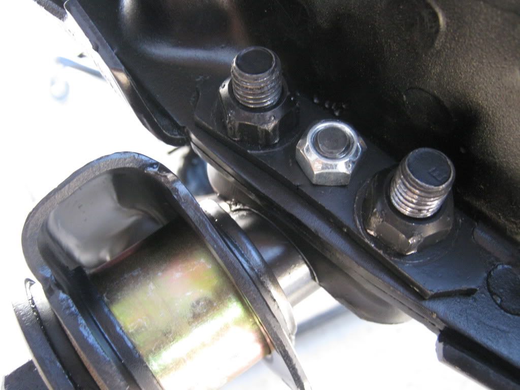 Here's a shot of the front side. You can really the .75" difference in position from stock. 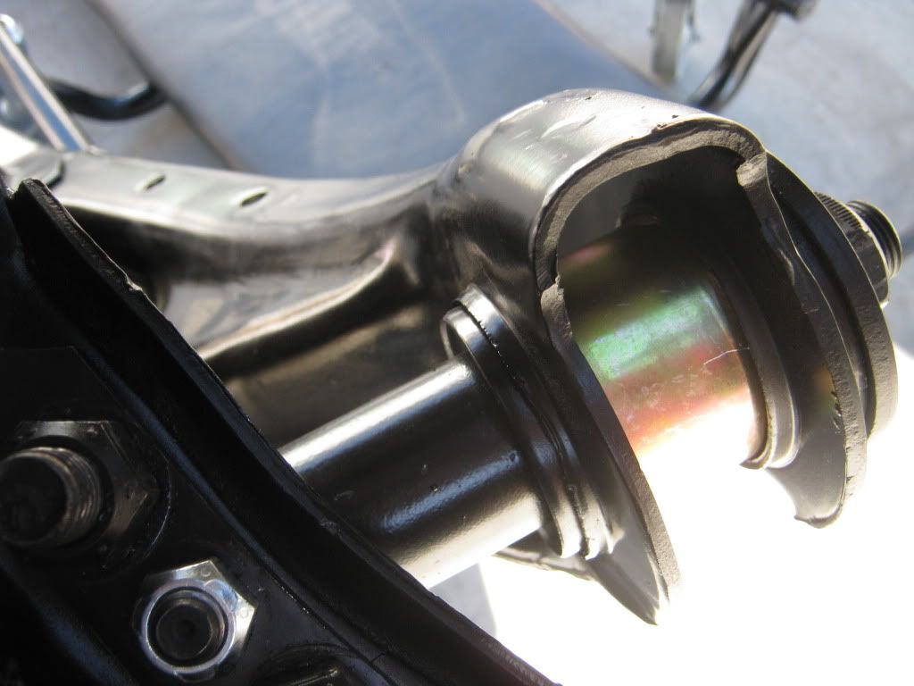 Here's another thing I did to eliminate a huge shim stack in the upper control arm. On the 1973-up half-tons, GM utilized spacers on the control arm bolts, along with the normal shims. Because I cut a coil from the stock spring, I knew that the alignment shop would have to add more shims to get the camber correct. So, I went to the wrecking yard and grabbed some other spacers(the fat ones) and added them to the mix. The original set-up was: 1 skinny spacer on the forward bolt, and one fat spacer on the rear bolt. The new set-up is: 1 fat spacer on the front, and 1 fat and 1 skinny spacer on the rear. Not much of a difference, but I don't like the look of a huge spacer stack on lowered vehicles. It moved the arms out about 1/4" of an inch. 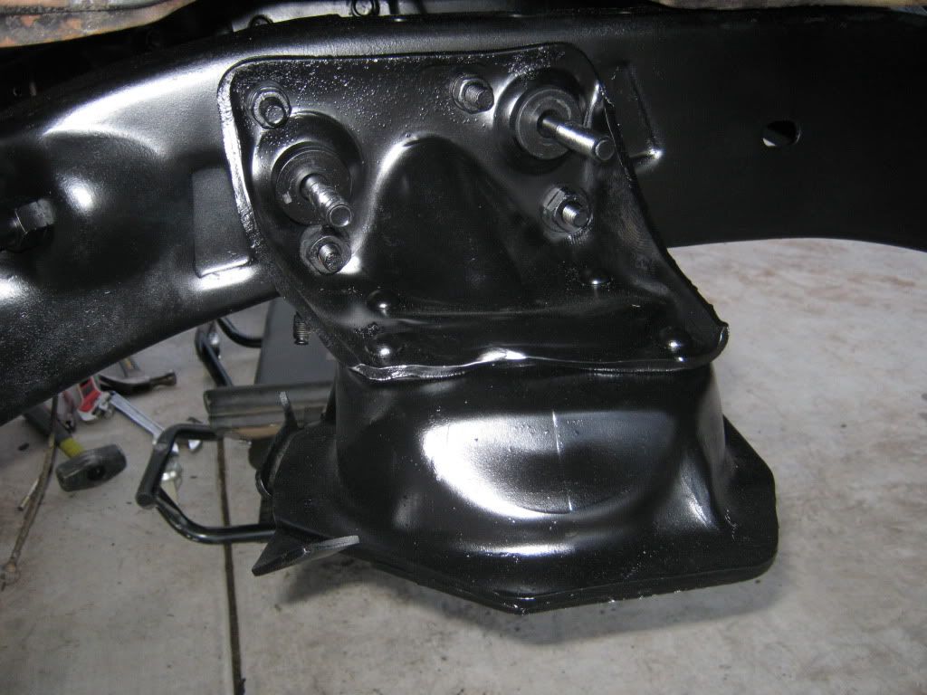 Not a great picture, but you can see the offset between the upper and lower balljoint centerlines. This shows you how much the spindle will tilt aft, thus increasing caster. 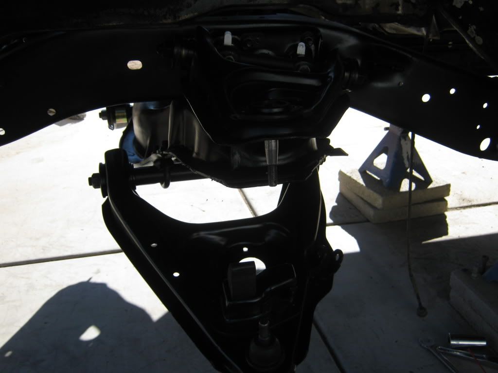 I'm not sure how much extra caster this mod will give me, but I think it will definitely be worth the effort. All told, I have right at $50 into this mod ($45 for the machine work, $5 for the nuts/bolts). I'm probably a couple of months away from being ready for the alignment shop, so I'll post up my results when I get them.
__________________
Check out my latest endeavor: https://roundsixpod.com My build threads: '55 Chevy: http://67-72chevytrucks.com/vboard/s...d.php?t=247512 '64 C-20: http://67-72chevytrucks.com/vboard/s...d.php?t=446527 Last edited by chevyrestoguy; 01-02-2012 at 03:19 PM. |
|
|

|
|
|
#2 |
|
Senior Member
 Join Date: Jul 2010
Location: Dandridge, Tn. USA
Posts: 2,226
|
Re: My caster mod (with pictures)
Looks great!! please keep us posted on the alignment specs. From my notes, you should be 6 to 7 deg static, and have some adjustment. Keep up the good work.
__________________
GoodGuys 2012 Pro-Truck Champion  2012 Truckin' Throwdown Champion GoodGuys 2011 National Champion  2011 Truckin' Throwdown Champion GoodGuys 2010 National Champion  Proud to put our products up against all others! |
|
|

|
|
|
#3 |
|
Registered User
 Join Date: May 2007
Location: Deale Md
Posts: 4,663
|
Re: My caster mod (with pictures)
This is on your 64 C20.
__________________
James 63 GMC V6 4speed carryall 65 chevy swb bbw V8 auto 68 K20 327/4 speed, buddy buckets 2002 GMC CC Dually Duramax 64 GMC lwb 3/4 V6 4speed SOLD 66 GMC swb bbw buddy buckets SOLD IG duallyjams The only thing that stays the same is constant change! |
|
|

|
|
|
#4 |
|
Registered User
Join Date: Sep 2011
Location: Jacksonville, FL
Posts: 150
|
Re: My caster mod (with pictures)
Great writeup! I think I speak for everyone whenever saying that writups with pictures are the best. I also look forward to seeing what caster numbers you achieve with this mod cause I plan to do this to my 84.
I do have one question. Why did you take the time to remove the u-bolt saddles and reattach them? Ive heard of quite a few people doing this LCA modification to gain caster and I haven't seen anyone mention that this step was needed.
__________________
Shawty: '84 C10 Silverado SWB, 700r4, SBC 350 - 4 bolt main, bored 60 over w/ Weiand aluminum intake and moderate cam, 2" true dual exhaust, Thrush mufflers, 3.42:1 gears -- Build Thread The Tranny (wrecked  ): '86 Trans Am, SBC 350 (now in above truck), Borg-Warner T-5, 2" true dual, Thrush mufflers, 2.73:1 gears ): '86 Trans Am, SBC 350 (now in above truck), Borg-Warner T-5, 2" true dual, Thrush mufflers, 2.73:1 gears
|
|
|

|
|
|
#5 |
|
A guy with a truck
Join Date: Sep 2005
Location: Germany, for now
Posts: 5,921
|
Re: My caster mod (with pictures)
Very nice write-up! Have you installed springs yet?
Oh, and PLEASE save the pics to the forum, so that they will be here for years to come 
__________________
-Chris Instagram _elgringoloco_ '70 Short-Wide How to: Ruin a perfectly good C10 ‘70 Blazer ConversionHow To: Ruin a Perfectly Good 4wd '72 Highlander How To: Ruin a Perfectly Good K/5 (SOLD) '72 Blazer 2WD How to: Ruin a perfectly good Blazer (SOLD) '05 Yukon Daily Driven (not so stock) Yukon (SOLD) ‘07 Yukon Denali (daily) Members met list: SCOTI, darkhorse970, 67cheby, 67cheby'sGirl, klmore, porterbuilt, n2billet, Fastrucken, classicchev, Col Clank, GSFMECH, HuggerCST, Spray-Bomb, BACKYARD88, 5150, fine69, fatbass, smbrouss70, 65StreetCruiser, GAc10boy |
|
|

|
|
|
#6 | |||
|
Registered User
 Join Date: Mar 2005
Location: apple valley, ca
Posts: 2,670
|
Re: My caster mod (with pictures)
Quote:
Yes sir. I did a crossmember swap on the '64 using a '79 Suburban as a donor. So essentially, this mod covers anyone using the '73-up half-ton front suspension. Quote:
Quote:
Mods-feel free to put this thread wherever you think it needs to go to be a reference.
__________________
Check out my latest endeavor: https://roundsixpod.com My build threads: '55 Chevy: http://67-72chevytrucks.com/vboard/s...d.php?t=247512 '64 C-20: http://67-72chevytrucks.com/vboard/s...d.php?t=446527 |
|||
|
|

|
|
|
#7 |
|
Registered User
Join Date: Jan 2009
Location: rocklin california
Posts: 142
|
Re: My caster mod (with pictures)
wont the spring rub on the pocket
|
|
|

|
|
|
#8 |
|
gets board easy.......
Join Date: Mar 2009
Location: Colorado Springs
Posts: 717
|
Re: My caster mod (with pictures)
I've done this. Not as detailed and clean as yours. I.didnt notice and spring rub.
Posted via Mobile Device |
|
|

|
|
|
#9 |
|
Grandpa in the rustmobile...
Join Date: Nov 2008
Location: Spokane WA/Viola TN
Posts: 11,422
|
Re: My caster mod (with pictures)
So im anxious to read the reviews, notice any difference lol?
__________________
John Goose-1968 C10 355,9.32-1CR, Vortec Heads ,262 voodoo, 3.73:1 3OTT (HS ride/beater/farm truck) http://67-72chevytrucks.com/vboard/s...d.php?t=317684 Grams 53-1953 Chevrolet Belair http://67-72chevytrucks.com/vboard/s...=1#post4327784 1969 Chevy C10 Shortbed 4.5/6?" Frame off resto http://67-72chevytrucks.com/vboard/s...d.php?t=548136 1999 Toyota Tacoma 4x4 |
|
|

|
|
|
#10 |
|
Senior Member
Join Date: Aug 2002
Location: Valley Center KS
Posts: 3,525
|
Re: My caster mod (with pictures)
Nice work! I'm planning on doing either this, or moving the ball joint on the LCA.
One thing, IMO the locating pin is most likely only there to aid in installation. Once you get the LCA u-bolts tight, I think they hold the shaft from moving front to back. So I don't think modifying the saddles is necessary, but it won't hurt anything either. |
|
|

|
|
|
#11 | |
|
Registered User
Join Date: Sep 2011
Location: Jacksonville, FL
Posts: 150
|
Re: My caster mod (with pictures)
Quote:

__________________
Shawty: '84 C10 Silverado SWB, 700r4, SBC 350 - 4 bolt main, bored 60 over w/ Weiand aluminum intake and moderate cam, 2" true dual exhaust, Thrush mufflers, 3.42:1 gears -- Build Thread The Tranny (wrecked  ): '86 Trans Am, SBC 350 (now in above truck), Borg-Warner T-5, 2" true dual, Thrush mufflers, 2.73:1 gears ): '86 Trans Am, SBC 350 (now in above truck), Borg-Warner T-5, 2" true dual, Thrush mufflers, 2.73:1 gears
|
|
|
|

|
|
|
#12 | |
|
Registered User
 Join Date: Mar 2005
Location: apple valley, ca
Posts: 2,670
|
Re: My caster mod (with pictures)
Quote:
Thanks. I had a co-worker tell me the same thing about the saddles, and although I can see where he's coming from, I had to disagree. To me, the locating pins serve a few purposes. First, they index the control arm at a certain location in relation to the center crossmember, which in turn, helps establish the factory-spec'd caster angle. Plus, they ensure that the rotation of the control arm occurs at the control arm bushing and not on the circumference of the shaft. If the rotation occurs at the circumference of the shaft instead of the control arm bushing, it will wear grooves in the shaft at the contact point with the saddles. If it wears excessively, then the shaft will become sloppy and wear out the other suspension components prematurely . True, the saddles/U-bolts hold the shafts tightly, but during the constant abuse that the suspension sees during normal use, they help to keep the lower control arms from moving from front to aft. If the control arm was only secured using the u-bolts/saddles and hit something hard directly on the forward face of the control arm, it could move the arm back slightly, changing the alignment. I may be over-thinking it, but I think the locating pins serve a very important function.
__________________
Check out my latest endeavor: https://roundsixpod.com My build threads: '55 Chevy: http://67-72chevytrucks.com/vboard/s...d.php?t=247512 '64 C-20: http://67-72chevytrucks.com/vboard/s...d.php?t=446527 |
|
|
|

|
|
|
#13 | |
|
Registered User
Join Date: Apr 2001
Location: DALLAS,TX
Posts: 22,080
|
Re: My caster mod (with pictures)
Quote:
__________________
67SWB-B.B.RetroRod 64SWB-Recycle 89CCDually-Driver/Tow Truck 99CCSWB Driver All Fleetsides @rattlecankustoms in IG Building a small, high rpm engine with the perfect bore, stroke and rod ratio is very impressive. It's like a highly skilled Morrocan sword fighter with a Damascus Steel Scimitar..... Cubic inches is like Indiana Jones with a cheap pistol. |
|
|
|

|
|
|
#14 |
|
Has more rust than truck...
Join Date: Apr 2005
Location: Ivanhoe, MN
Posts: 2,421
|
Re: My caster mod (with pictures)
Thanks for the write up!
|
|
|

|
|
|
#15 |
|
Registered User
Join Date: Jun 2007
Location: DFW (Forney)
Posts: 1,529
|
Re: My caster mod (with pictures)
Agreed
Great write up, and great mod. Be sure to keep us posted with results.
__________________
'58 SWB Fleetside...Front & Rear Porterbuilt Dropmember, 6.0 LS /4L60E. Accuair E-level, 20 Billet Specialties (Vintecs) '63 Buick Riviera ... AccuAir E-level, 20" Billet Specialties (Vintecs) http://67-72chevytrucks.com/vboard/s...=528853&page=5 |
|
|

|
|
|
#16 | |
|
Registered User
Join Date: Jan 2012
Location: Portland, OR
Posts: 38
|
Re: My caster mod (with pictures)
Quote:
My question is, will we experience undesirable toe-out on turns readings by taking the steering arm on the spindle out of alignment with the pitman arm/center link/idler arm assembly? It seems to me that given the triangular geometry we will create by doing this, the outer wheel will want to turn at a greater angle than design, while the inner wheel will want to turn at a lesser angle. The setup of my 1982 C10 is shown, with the steering linkage in front of the wheel center axis.  Your thoughts? Mike Last edited by Mike_82_Shortbox; 01-12-2012 at 12:39 AM. |
|
|
|

|
|
|
#17 |
|
Registered User
 Join Date: Mar 2005
Location: apple valley, ca
Posts: 2,670
|
Re: My caster mod (with pictures)
Mike-
That's a great question. I'm going to have to draw this out on paper and visualize the linkage. Moving the arm back .75" will effectively move the tie rod attach point on the spindle up slightly and slightly to the rear. Because the change is occuring at an arc, the collective position change in the upward and rearward direction is very small. What I need to do is to install the linkage completely on the truck and see if I have an ackerman condition. If so, I could probably shift the idler arm on the passenger side frame rail to compensate, but the pitman arm on the steering box determines the position on the driver side, and that could get tricky. I believe that the combination of the ball-joint unions on the tie rods and the idler can compensate for the slight alignment change, but until I put the linkage together and see for myself, I'm not 100% convinced. I'm very interested to get more opinions on this, so feel free to post up any opinions, theory, or data.
__________________
Check out my latest endeavor: https://roundsixpod.com My build threads: '55 Chevy: http://67-72chevytrucks.com/vboard/s...d.php?t=247512 '64 C-20: http://67-72chevytrucks.com/vboard/s...d.php?t=446527 |
|
|

|
|
|
#18 |
|
Registered User
Join Date: Feb 2007
Location: Memphis MI
Posts: 1,851
|
Re: My caster mod (with pictures)
Didn't you move the LCA forward? That would move the tie rod attachment forward?
__________________
1987 2 ton  1982  250/TH350 beater in progress 250/TH350 beater in progressDad's 1981  3/4 L6 3 on tree posi and no options, awaiting restoration or scrapping 3/4 L6 3 on tree posi and no options, awaiting restoration or scrappingPlus a mess o' tractors |
|
|

|
|
|
#19 |
|
Registered User
Join Date: Apr 2001
Location: DALLAS,TX
Posts: 22,080
|
Re: My caster mod (with pictures)
No.... He just moved the lower forward.
__________________
67SWB-B.B.RetroRod 64SWB-Recycle 89CCDually-Driver/Tow Truck 99CCSWB Driver All Fleetsides @rattlecankustoms in IG Building a small, high rpm engine with the perfect bore, stroke and rod ratio is very impressive. It's like a highly skilled Morrocan sword fighter with a Damascus Steel Scimitar..... Cubic inches is like Indiana Jones with a cheap pistol. |
|
|

|
|
|
#20 | |
|
Registered User
 Join Date: Mar 2005
Location: apple valley, ca
Posts: 2,670
|
Re: My caster mod (with pictures)
Quote:
Only the lower arm was moved forward, so it rolled the tie rod attach point on the spindle slightly up and back. To visualize this, get two pencils and tape them together like a cross. Then, place them between your two index fingers and then move the lower finger slightly forward. If I moved both lower and upper control arms forward an equal distance, the tie rod attach point would be moved forward because the spindle moved the same distance.
__________________
Check out my latest endeavor: https://roundsixpod.com My build threads: '55 Chevy: http://67-72chevytrucks.com/vboard/s...d.php?t=247512 '64 C-20: http://67-72chevytrucks.com/vboard/s...d.php?t=446527 |
|
|
|

|
|
|
#21 |
|
Account Suspended
Join Date: May 2011
Location: Streator, IL
Posts: 78
|
Re: My caster mod (with pictures)
chevy, what is the over all caster angle in this mod compared to stock? im building a front stub on my 86 and want to build control arms but only build them once. im looking for a good angle to set up my arms. any help would be greatly appreciated.
thanks |
|
|

|
|
|
#22 |
|
Registered User
 Join Date: Mar 2005
Location: apple valley, ca
Posts: 2,670
|
Re: My caster mod (with pictures)
In post #2, Rob says that I should have between 6 and 7 degrees static, with some additional degrees possible after adjustments.
__________________
Check out my latest endeavor: https://roundsixpod.com My build threads: '55 Chevy: http://67-72chevytrucks.com/vboard/s...d.php?t=247512 '64 C-20: http://67-72chevytrucks.com/vboard/s...d.php?t=446527 |
|
|

|
|
|
#23 |
|
Still plays with trucks
Join Date: Jul 2009
Location: Spokane, WA
Posts: 3,556
|
Re: My caster mod (with pictures)
Nice work. Thanks for the write up and pics.
__________________
miSSed opportunity - ground up creation of an AWD 1994 454 SS that never was http://67-72chevytrucks.com/vboard/s...d.php?t=795577 69 C10 shortbed stepside 400 small block - built like what a super sport truck could have been 69 K20 lwb TBI 350 4L60E NP208 14-bolt Dana-44 w/disc 68 Camaro SS / RS 500hp 439 inch roller cam big block 4L80E 79 Malibu TPI 350 4L60 w/ Z28 steering & sway bars |
|
|

|
|
|
#24 |
|
At the body shop.
Join Date: Aug 2009
Location: Land of fruits and nuts.
Posts: 5,271
|
Re: My caster mod (with pictures)
Just had a thought.... this mod would center my tires in the fender.
That has bothered me since i put the 6° of caster in. Posted via Mobile Device
__________________
" That didnt make it any newer " " Dont antique the equipment " |
|
|

|
|
|
#25 | |
|
Registered User
Join Date: Sep 2011
Location: Jacksonville, FL
Posts: 150
|
Re: My caster mod (with pictures)
Quote:
Posted via Mobile Device
__________________
Shawty: '84 C10 Silverado SWB, 700r4, SBC 350 - 4 bolt main, bored 60 over w/ Weiand aluminum intake and moderate cam, 2" true dual exhaust, Thrush mufflers, 3.42:1 gears -- Build Thread The Tranny (wrecked  ): '86 Trans Am, SBC 350 (now in above truck), Borg-Warner T-5, 2" true dual, Thrush mufflers, 2.73:1 gears ): '86 Trans Am, SBC 350 (now in above truck), Borg-Warner T-5, 2" true dual, Thrush mufflers, 2.73:1 gears
|
|
|
|

|
 |
| Bookmarks |
|
|